
ROG Ally 80W Battery Upgrade
This is an overview and guide on installing the Ally X battery into your OG Ally. Asus has added an enable circuit to the Ally X battery.
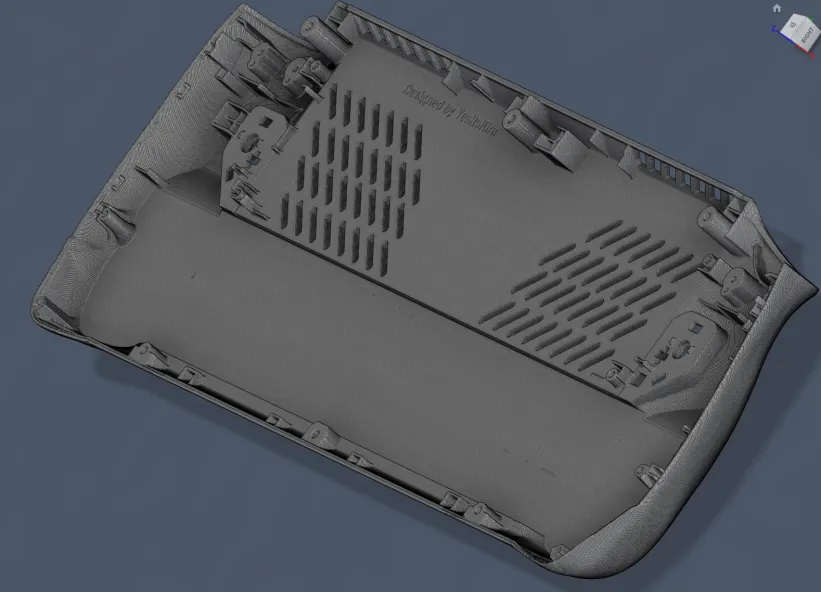
- Designed with cooling and longevity in mind.
- Dedicated air intake vents, and cooling channels to keep battery and RAM temperatures down. Newer battery cells.
- Less weight than other battery mods.
- Can be used with a factory back panel.
- No need to fold or reconfigure battery like other mods.
- No backplate hump like other battery mods.
There are currently two options for this mod. You can print what we call the wedge which will let you use a backpanel like the one JSAUX sells or you can 3D print an entire back panel. Currently, we have the prototype back plate, wedge, and battery tray available on our discord server for those with a 3D printer or who want to have it printed 3rd party. You will need to snip the blue wire (pin 3) and run it to any clean ground point on the Ally. The best point to do this is Pin 8 (far black wire) This will tell the ally X battery to turn on. If you don’t wish to solder please reach out to the discord server to try out a cable adapter that’s in very early development.
Credit:
- Tekgnome – Inventor/Project Lead, Tester,
- LowKeyLoki – Help with BMC and testing
- YesItsKira – Lead Backplate, and Wedge Designer (Donate Here)
- Seth – battery trey designer with cooling channels.
- DesignGears – alternative battery trey designer
Materials needed:
- FDM or SLA printer
- Phillips size 100 driver
- Plastic pry tool
- OEM Charger
- Download the STL files (Not Available for public download yet, join the handheldmodz discord server to help test)
- 3D printed ThiccPlate or Wedge
- 3D printed Printed battery trey
Notes:
- For the ThiccPlate, you will need the printed back panel, printed battery tray, and printed modified paddles.
- For the Wedge, you will need the printed wedge, printed battery tray, and printed paddle extenders.
- The Red “warranty void” sticker on the battery and heat pipe does not void your warranty provided you do not damage anything inside of the device and restore it to a factory original condition before the RMA
- You will need to self-tap the screws into the printed part, FDM might require heat, SLA will require you to do this before you cure the part.
- Be extremely careful when removing the back panel screws, paddle, and trigger screws as they can strip!
- DO NOT SHORT PIN 3 to ground or you will cause the battery to fall into fault mode!
- DO NOT USE LONGER screws for the wedge if you accidently mix them with the top ones as they will go through the shell and into the screen destroying it.
- BY FOLLOWING THIS GUIDE YOU TAKE RESPONSIBILITY FOR YOUR OWN ACTIONS
Instructions:
- Option 1: ThiccPlate and Printed Paddels. Installing the printed paddles into the printed shell In order for the new battery to fit we had to make some minor adjustments to the back paddles. This will require you to have a set of paddles printed or you can print them yourself. We plan to offer two stl’s to pick from on YesItsKira’s thingyverse. Remove the existing paddles from your original back panel, be sure to be VERY careful as the screws are easy to strip Install the printed paddles with the screw and springs from your original paddles into the printed back panel
- Option 2: The Wedge This option will let you reuse the stock battery panel or use other back panels like the transparent ones from JSAUX or HandHeldDIY The Wedge will require 3x M2x18 screws ONLY for the bottom 3 screws. Use stock for top 3. You will need to snip off the supports from the HandHeldDiy or OEM Backpanel. The Jsaux one doesn’t have any supports over the battery and doesn’t need to be trimmed.
Soldering the Ally X battery
This is optional, you can reach out to the discord server. A plug and play adapter will be available soon. Please be aware that handheldmodz doesn’t sell or offer any services, when buying from 3rd party sellers. Cut pin 3 (blue wire) midway. Be sure to cover the wire motherboard connector side with electrical tape (or depin it) as the ally has it wired to give 17v and it will cook your battery if it accidentally shorts (I found this out the hard way, it is possible to take it out of fault mode but its a pain) Solder pin 3 to pin 8 (black) Don’t cut pin 8 just scrape away a bit of the wrap and solder it so pin 3 has continuity to the blue wire going into the battery.
This little guy right here is what’s looking for the enable pin to ground Snip blue wire, expose black wire shielding Solder battery side blue wire to exposed black wire tape over soldered wires tape over blue wire connector side so it cant short
wrap everything in tape securely The appropriate wire soldered to ground (pin 8 black wire). Pic provided by Tekgnome. Soldering iron optional.
Installing the battery and printed back panel
You can check out this awesome ROG Ally teardown video by ifixit:
- Remove back panel
- Unplug the factory battery
- Remove Factory 40Wh battery (If your Ally X battery has a battery tray you’ll want to remove it.)
- Install the printed battery Trey
- Lay the Ally X 80Wh battery in place
- Plug-in Ally X battery. There may be a small spark when plugging it in for the very first time, this is normal as the BMC is already active.
- Install the wedge or install the ThiccPlate back panel
- Test fit everything
- Close the modified shell and put the screws back in
- Plug in OEM charger and hold the power button until the screen turns on.