ROG Ally - Micro SD Card Fix
Fix your ASUS ROG Ally microSD card reader with our step-by-step guide to restore full storage and performance.

This is a guide and general overview of the fault with Asus Micro SD card reader, or more so the issue with the PTC fuse that causes the reader to no longer be able to read Micro SD cards, and sometimes potentially causing damage due to corruption. Unlike what has been reported, this failure isn't typically caused by heat, but rather a combination of a slightly undersized PTC fuse and not enough solder on the joints of the fuse. This guide will cover how to reflow the fuse to ensure a good connection and has had great results in restoring dead micro SD card readers.
Credit:
- ZuwaiiVR (original Reddit post)
- LowKeyLoki — Found the correct fuse fix and shared the reference shots.
- ΜỮŞĦƗΜΔŞŦ€ŘǤƗŇҜØ Pictures and testing (for reflow fix)
- YesItsKira - Teardown Pictures (Donate Here)
Materials needed
- ESD wrist strap and anti-static mat
- Temperature-controlled soldering iron (small chisel or conical tip ~1.5–2.4 mm)
- Optional hot-air station (helpful for SMD PTCs)
- Desolder braid (solder wick) + flux (rosin/no-clean)
- Solder: 0.5–0.6 mm (lead-free) or 0.5 mm 63/37 eutectic (if you choose leaded)
- Fine tweezers, magnifier/microscope or loupe
- Kapton tape (protect adjacent parts)
- Isopropyl alcohol (90%+) and a small brush or lint-free swabs
- Multimeter (continuity/resistance)
- Thin hookup wire and small soldering needle for pad repair (optional)
- Phillips size 100 driver
- Plastic pry tool
- PTC Fuse Part # SMD0805B100TFT
Notes:
- We recommend, if at all possible, to RMA your device before attempting this fix
- You may reflow the existing fuse, which may fix the problem, or for a more permanent solution, you can replace the PTC fuse with an updated part that doesn't have these issues.
- BY FOLLOWING THIS GUIDE, YOU TAKE RESPONSIBILITY FOR YOUR OWN ACTIONS
- This will void your warranty.
- This is an advanced mod if you feel overwhelmed at any point while reading this, you should walk away.
- This guide is under construction. Please keep this in mind as you read through it.
Instructions:
Remove the back panel and unplug the battery
Remove the six screws holding the battery in place and remove it.
Remove both joystick boards
- 3 ribbon cables
- 4 screws
Remove motherboard
- Unplug the speaker cable
- Unplug fan headers
- Remove fan screws.
- Remove fans.
- Unplug two cables coming from the wireless card
- Remove both motherboard ribbon cables.
- Remove all 9 motherboard screws.
- Tilt and life motherboard out of shell.
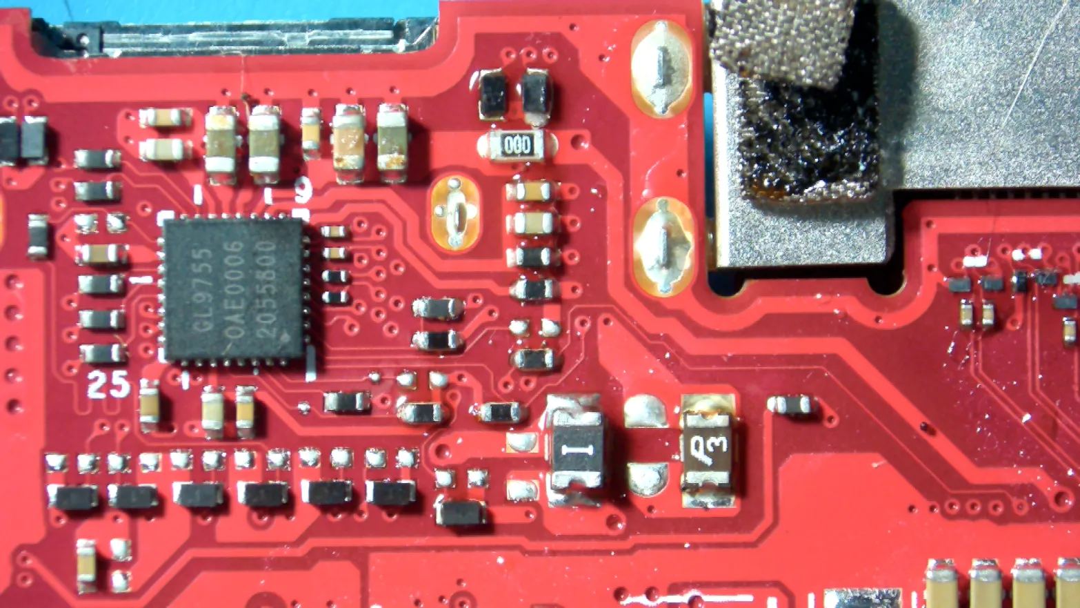
From here, we can reflow the fuse or preferably replace it completely with the updated part. It's the one closest to the Genesys logic controller on the back side of the main board. The fuse in question is a littelfuse 0805L075SL
Option 1: Replace Defective Fuse
Desolder / remove the old PTC fuse
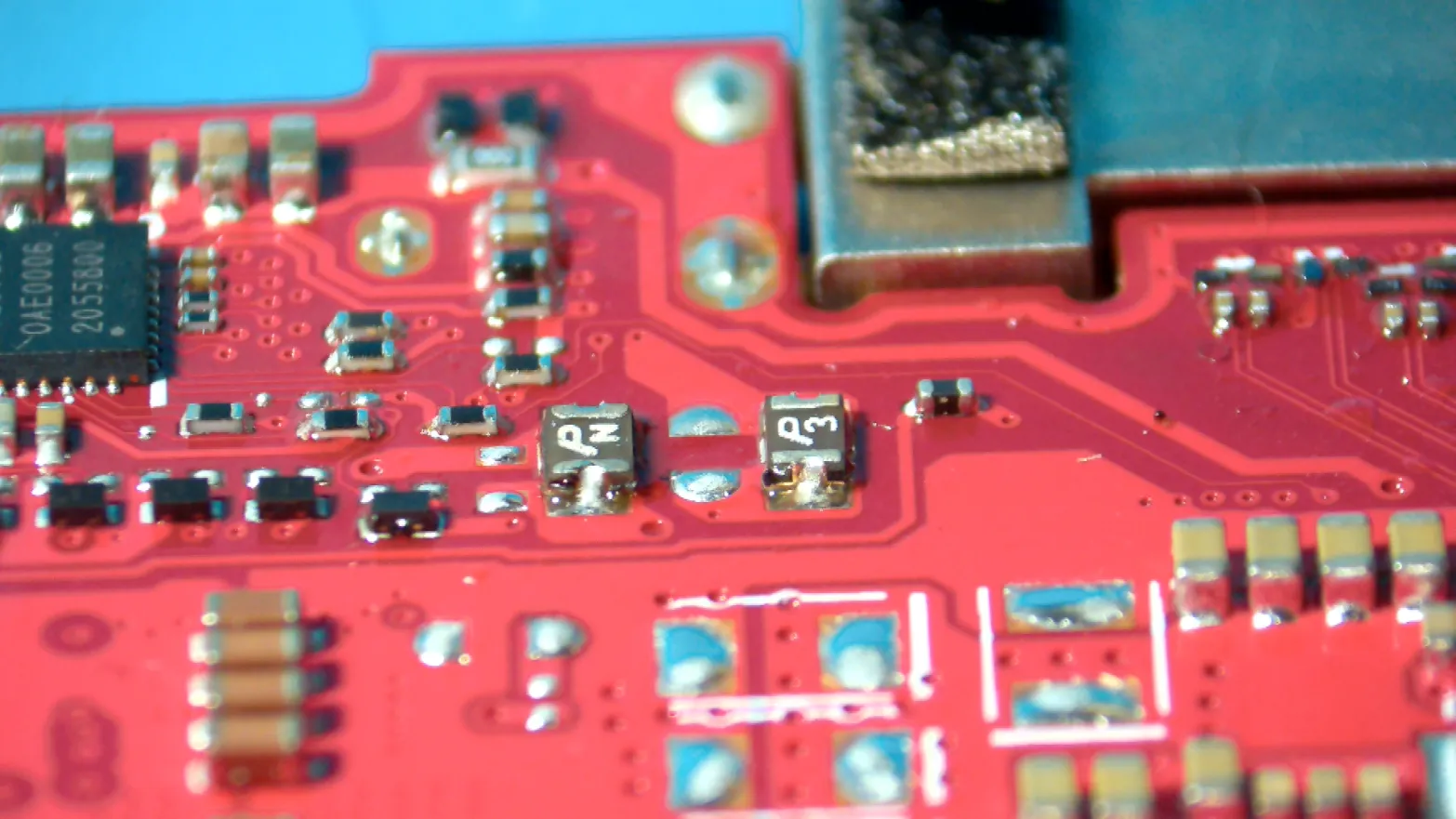
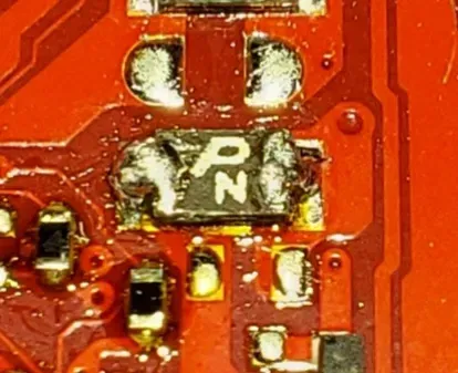
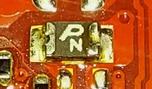
Stock Fuse Pictures, Please note that we will be replacing "Pn" in the above board
- Work in a well-ventilated area and use a fume extractor.
- Apply Kapton tape to protect nearby chips/components that could be disturbed by heat.
- Apply a small amount of flux to the defective fuse terminals and pads. Flux helps heat transfer and solder flow.
- Method A — Soldering iron + braid (recommended when pads are intact):
- Place solder braid over the pad/terminal, press the iron tip on top of the braid so heat transfers through to the joint.
- Move the braid steadily; it will absorb molten solder. Replace braid section as it saturates.
- Repeat on both terminals until solder is cleared and the fuse is loose.
- While heating one pad, gently pry the fuse with tweezers to lift it once the solder is molten — lift quickly and evenly.
- Method B — Hot air (recommended for stubborn or multi-terminal joints):
- Mask nearby components with Kapton tape. Preheat board if you have a preheater (100–120°C).
- Set hot air to ~300–320°C for lead-free solder (or ~260–300°C for eutectic 63/37). Use low airflow to avoid blowing parts.
- Heat evenly until solder flows, then pick the fuse up with tweezers.
- Let the board cool naturally; don’t move the part until solid.
- After removal, clean pads with solder braid to remove remaining solder, then wipe with IPA and a brush.
Inspect the pads
- Use magnification to inspect the copper pads. If pads are lifted or damaged:
- Stop and repair the pads before installing the new fuse.
- Simple pad repair: scrape mask to expose fresh copper, tin lightly, or tack a tiny wire to rebuild the trace, then solder fuse to the repaired area.
- If pads are badly lifted, consider using a donor pad or jumper to an alternative test point.
Prep & solder the replacement PTC fuse
- Confirm the replacement fuse has the same footprint and similar trip/current rating (or the rating you intended). PTCs are typically non-polar, but check for markings and datasheet if in doubt.
- Lightly tin each board pad (apply a very small amount of solder) or just have flux ready — some techs prefer pre-tinning the new fuse legs instead:
- Pre-tinning fuse terminals: hold the fuse with tweezers, touch a tiny amount of solder to each terminal so it’s pre-tinned (be conservative).
- Position the new PTC with tweezers onto the pads; use Kapton to hold it if needed.
- Tack one end first:
- Apply flux, touch the soldering iron to the pad and fuse terminal simultaneously, feed a minimal amount of solder so it forms a secure tack. Remove iron and let cool — this secures alignment.
- Solder the second end:
- Heat pad + terminal together, feed solder to the joint, create a small, smooth fillet. Do not blob solder — keep it neat.
- Reflow the tack if necessary so both joints look even and properly wetted.
- Recommended iron temps: aim for ~320–350°C if using lead-free solder; ~280–320°C for 63/37. Use the lowest temperature that reliably melts your solder to reduce heat stress on nearby components.
Post-solder cleaning & inspection
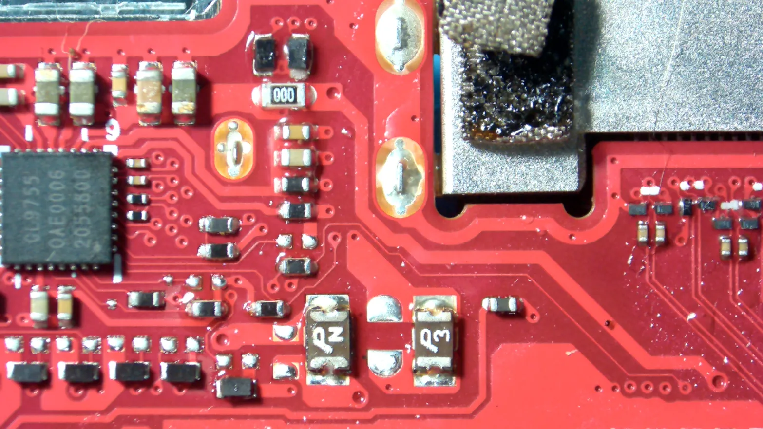
New Fuse should look like the above mainboard picture
- Inspect joints under magnification:
- Good joint = smooth fillet, clean wetting of pad and terminal, no solder bridges, no cracked or dull grainy surfaces that indicate cold joints (note: lead-free looks duller than leaded).
- Clean flux residues with IPA and a brush.
- Check for accidental bridges or solder splashes on nearby pins.
Electrical checks before reassembly
- With the board powered only after battery reattachment / bench power (be cautious):
- Measure continuity across the PTC — it should read low resistance (near short) when healthy; if it’s very high, it may be open or tripped.
- If you have a bench supply, you can power the rail and watch current draw for abnormal signs before full reassembly.
- Insert a microSD (if safe) and test detection after reassembly / power on. Monitor for correct behavior.
Option 2: Reflow Fuse
We will resolder both sides of the fuse. This was an older method of reviving a dead reader and is only really recommended if you absolutely can't afford to just replace the defective fuse with the updated part.
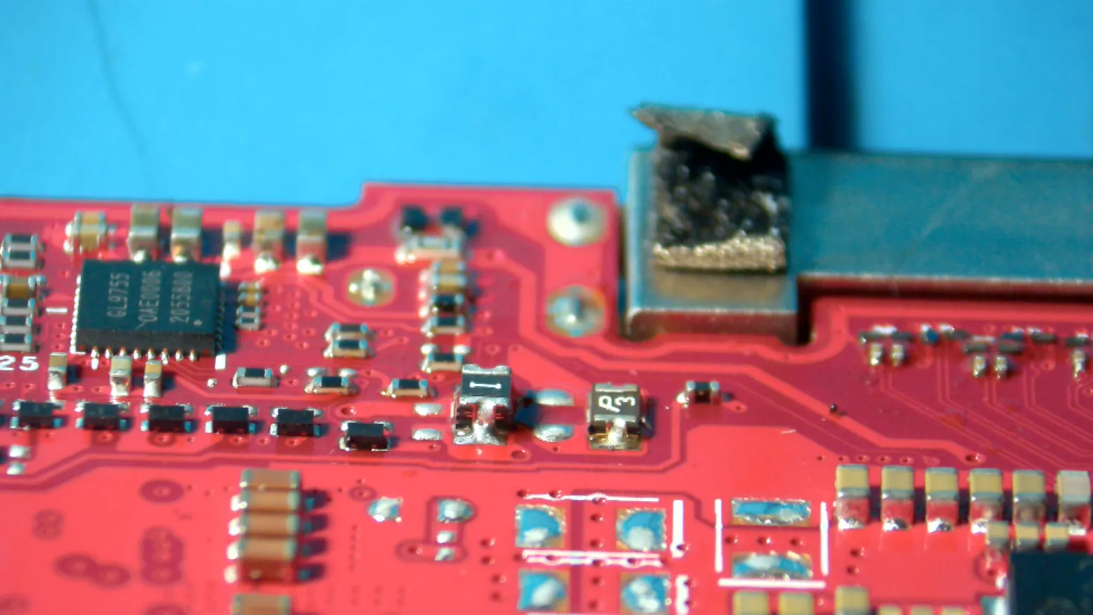
This is what it should look like before being reflowed once. You can see significantly less solder on the left side, so let's fix this.
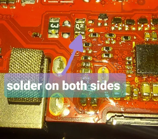
After soldering on both sides, it should look like this.