
Sony PSP Go Shell Replacement Tutorial
This tutorial is an in-depth guide on how to replace your PSP Go's shell. These aftermarket shells tend to have lower quality parts than the OEM shell so it's a good idea to mix and match parts depending on what fits and looks best such as the buttons and screws.
Credit:
- YesItsKira
Notes:
- The joystick doesn't come with the replacement shell and is one contained part. If you are changing the shell, it may be a good idea to buy a new joystick.
Materials Needed:
- Precision screwdriver set
- Plastic pry tool
Instructions:
1. Unscrew the 4 screws on the back of the PSP Go and the two screws at the top.
2. Pop off the back of the Go.
3. Gently pull off the top bar that has the volume and brightness buttons on it.
4. Remove the warranty sticker. It may leave a residue but that is ok.
5. Using something pointy like a flathead screwdriver, pop up the latch for rb and lb and carefully pull the ribbon out of the connector.

6. These parts hold in the bumpers with one screw for each. Unscrew and remove them and remove the actual buttons.
7. The battery is not secured so can just be lifted out.The connector for the battery needs to be lifted directly up. You can use something like a flathead screwdriver to make this easier.
8. Now carefully peel off the sticker that sits under the battery and remove the screw to take out the holder.
9. Now remove the two screws holding in the bottom bar.The bar is also clipped in on either side but you can remove it just by wiggling it if it is stuck.
10. Next, you can very gently peel off and clean the membranes that are stuck to where the lb and rb sit.
11. Unscrew the two screws shown below.
12. The headphone jack ribbon is not secured in the connector with a latch. It can just be carefully pulled out as it is held in with friction.
13. The joystick will also now be loose and the ribbon can be disconnected the same way as the lb and rb latch.
14. There is also a ribbon cable friction connector that goes around the main board. Carefully unplug this.
15. Also remove the friction fit ribbon cable that goes to the top of the Go.
16. The screen connector is on the other side of the board. Lift the board and press down on the ribbon to disconnect it and remove the whole board.
17. Take out the dpad and abxy buttons.
18. Remove the below 4 screws to separate the midsection and the front of the Go.
19. Peel the blue ribbon cable for the buttons off the top of the device.
20. The start and select are held in with tape. Using something sharp, push the two membrane out from the other side.
21. The actual ribbon for the start and select can be very carefully peeled off the frame.
22. Next remove these 4 screws.
23. The front screen housing is held to the frame with the screws we just removed and also clips. Separate them by using a guitar pick or plastic pick around where they meet while pressing on the screen. Eventually the two will separate.
24. Remove the speakers using a flathead screwdriver.
25. Unplug the connector next to the screen and then the screen can be removed if you want to replace it.
26. Take the new front shell and put the speakers in making sure that the speakers are in the orientation shown below.
27. Add the PS button that you would like to use making sure that the plastic posts go through the holes in the membrane.
28. If you are adding a new screen, this is where you would remove the screen protector.
29. Press the front housing onto the screen and press around the edges to make sure that the clips click in.
30. Screw these screws in to hold the front shell to the screen housing.
31. Put the midframe back on making sure that the screen ribbon is not caught underneath and screw in these 4 screws to connect the two parts.
32. Add your power and internet buttons back into the assembly.
33. Restick the blue ribbon back to the top of the go.
34. Now click the top bar back into place over the ribbon.
35. Thread the start select ribbon through the assembly and stick it down making sure that the posts line up with the holes in the membrane and stick the start select buttons down over that making sure that they are aligned.
36. Add the dpad and abxy that you would like to use. The dpad has no orientation however make sure to put the abxy in the right way.
37. Place the motherboard above the assembly like in the picture below to easily plug in the screen connector.
38. Flip the motherboard downwards onto the assembly making sure that the ribbon cables stay above the board.
39. Reconnect the blue ribbon and the ribbon coming from under the board into their friction fit connectors.
40. Now plug the joystick back in making sure to lift the latch before and pressing it down to secure the ribbon and insert the headphone jack ribbon into its friction fit connector.
41. Now you can screw the joystick and headphone port in.
42. Screw in the metal bracket and add the new separator that came with the new shell. It will go over the blue ribbon.
43. Now you can stick down the new sticker that came with the shell.
44. Make sure that the power and internet buttons are interfaced correctly with the buttons on the motherboard.
45. Plug in the battery and lay it in the housing.
46. The two bumper membranes have slightly different ribbon cables.The picture below shows which side is which. Stick down the membranes making sure that they are aligned correctly.
47. Add the Lb and Rb buttons.
48. The two parts that secure the buttons are different for each side. The picture shows which side is which. These go under the ribbons for the membranes and can be screwed in.
49. Insert the ribbons and close the latches.
50. Clip the bottom bar into place and screw it in.
51. Finally, press the backplate and screw the four longer screws into the back and the two shorter screws into the top.
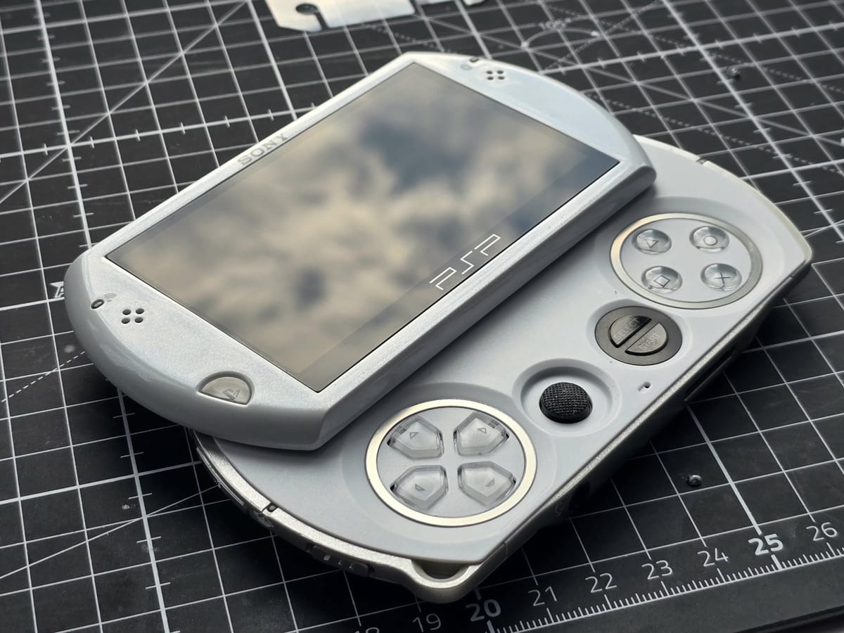
52. Your PSP is complete! Enjoy!